Our project consists of a controlled environment hydroponics system calibrated to grow spinach. We aim to use this project to create an in-home garden that efficiently grows vegetables integral to our everyday diets.
Table Top Garden
Jessica Henson & Leo Davies | Electrical and Computer Engineering College of Engineering, Cornell Univ.
This article covers the design and construction of a countertop-controlled environmental hydroponic system for growing fresh produce in your home all year round! Consisting of a 12x12x16-inch box, our in-home garden is equipped with sensors and actuators for controlling water temperature, water level, and light resources. We affect these environmental conditions by means of two fans, a water pump, heat pads, and lights. A proportional controller automatically adjusts these devices to maintain a stable internal environment as measured by temperature, humidity, and ultrasonic sensors. A Raspberry Pi Pico controls the whole system. We hope that a simple greenhouse-like appliance might someday be as common as microwave ovens, helping with produce agriculture and thereby reducing the carbon footprint associated with this area of agriculture.
High-Level Design and Technical Details
This project, completed as a four-week assignment for our microcontrollers class, combined our mutual interests in hydroponics, indoor growing systems, and embedded systems engineering. Mechanically, our system includes a 12x12x16-inch cubic acrylic box, with small holes cut out for wires, tubes, and fans, and a hinged front door to access the contents within. We made our hydroponic reservoir, depicted in Figure 1, out of a store-bought Tupperware container, with holes cut out of the lid to accommodate grow cups. After researching online, we found the most important elements to maintain were constant water level and temperature. We separated these into two control loops, with a sensor to detect current values, and actuators to react to sensor readings.
For the water level control loop, we found that an ultrasonic sensor, the Adafruit HC-SR04, could read distances off liquid surfaces. We also found a cheap submersible water pump from Ledgle that could be placed in a separate nutrient water reservoir, and pump water into our system. We ran a tube from our external pump into the reservoir our plants grew in to allow the pump to refill the water levels. Figure 1 depicts this system. The ultrasonic sensor sends out an ultrasonic signal and awaits its reflection off a surface. Using this time the signal took in junction with the speed of sound, and the distance between the sensor and the surface can be calculated.
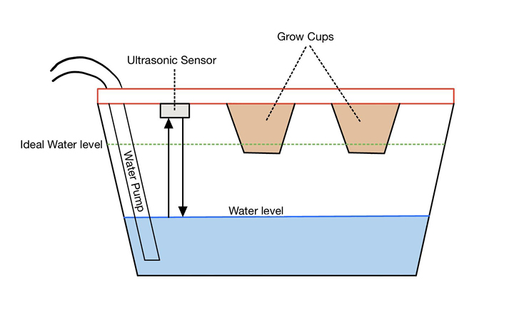
Figure 1: An illustration of the ultrasonic sensor reading water levels. In the situation
pictured above, the sensor would notice a low water level, relay that information to the microcontroller, and the microcontroller would turn on the pump until the ideal water level is reached.
For the temperature control loop, we found a temperature sensor, the 1-wire DS1820, that could give us readings in both Celsius and Fahrenheit. To control and maintain the temperature, we needed actuators to both cool and heat the system. To cool our system, we inserted fans into the walls of our enclosure to provide cool airflow. To heat up our system, we placed gentle heating pads underneath the grow reservoir. Pictured below is a high-level block diagram of these two control loops, all integrated with a microcontroller. We used a Raspberry Pi Pico, but most commercially available microcontrollers would work as well.
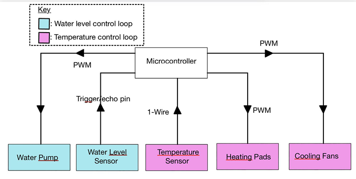
Figure 2: High-level block diagram of our control system. The arrows indicate the
direction of data and control flow.
Each additional device added a bit of complexity to the system. Although most microcontrollers have a large number of GPIO (general purpose input/output) pins, they cannot be mapped to arbitrary internal signals. It is important to consider which signals are being used in the system and which are available when adding hardware to the system.
One other extremely important consideration we had while selecting devices was the safety of the electronics. Our devices and systems were working near water, so we had to think about how to thoroughly protect our devices without compromising their functionality. This was part of the motivation for our enclosed box, which we designed using 3D modeling software, to keep the electronics isolated outside from the humid and wet environment inside the box. Our microcontroller and circuit board were located on top of the box, with a hole in the box allowing the enclosed wire to run in and connect to the heating pads and the ultrasonic sensor. Keeping< the circuit on top kept it isolated. The water pump, located in an external reservoir far from the electronics, used a tight seal tube to deposit nutrient water directly into our grow reservoir. All of these design choices ensured a safe environment for our electronics to operate in.
The software design for our system involved two closed-loop (maintains itself through sensor readings, not external input) control systems for the water level and temperature. For our temperature control loop, we had a user interface that awaited input on the desired temperature for the environment. Upon receiving the desired temperature, let's call it 𝑇 , it would compare 𝐷 that to the current temperature reading from the sensor, 𝑇 . If was less than , the heating 𝑆 𝑇𝑆 𝑇𝐷 pads would turn on. This loop continued until 𝑇 equaled , upon which the heating pads would 𝑆 𝑇𝐷 turn off. The same thing would happen with the cooling fans if was 𝑇 greater than . The user 𝑆 𝑇𝐷 could change the desired temperature at any point if desired, and the system would respond accordingly. Our system was designed with the idea that a user could set the temperature for the type of produce they were growing, not touch it again, and the system would reach that temperature and stay there for an extended period. A future addition to our system would be a hysteresis region that would require the temperature to drop or rise a couple of degrees from the desired temperature before turning on an actuator to prevent small variations in temperature causing constant oscillations on and off for the devices.
For our water level control loop, no user input was required. Instead, the system would purely read the measurement of the ultrasonic sensor and compare that to a set level that would keep the roots and base of the grow cup in the water. If the ultrasonic sensor read a low water level, our system would turn on the pump until that level was reached, upon which it would turn off the pump to not overflow the system. This also meant that if a user turns on the system for the first time with an empty grow reservoir, this would be resolved right away by the ultrasonic sensor and fill it with water. The pump could be placed in a reservoir with nutrient water to feed the plants. These two control loops were integrated in parallel in our software system so they could both run simultaneously.
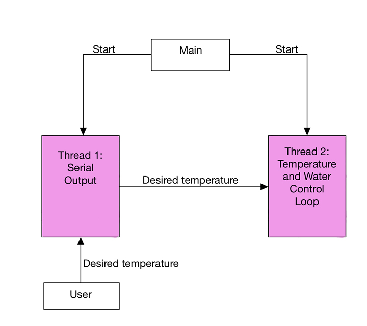
Figure 3: A high-level block diagram of the software. A main section starts two threads that run
indefinitely. Thread 1 waits for user input while thread 2 runs the control loops without
interruption.
Results
While this project was just a prototype, we were overall satisfied with the turnout. We were successfully able to control the level and temperature of the water. We have plans for controlling the nutritional content of the water through a TDS sensor and the humidity level through a humidity sensor. This design allows for the plants to grow unmonitored by humans till full maturity.
Because our interest lay in how a device like this would affect carbon emissions, we decided to calculate the carbon cost of growing a pound of spinach and the cost of growing, packaging, and delivering a pound of spinach. According to the article “What is the Carbon Footprint of Spinach? A Life-Cycle Analysis” by Grace Howarth, the overall carbon footprint for a pound of spinach is 0.3 kg of carbon dioxide. This includes about 0.08 kg for growing, 0.10 kg for harvesting, processing, and packaging, and 0.12 kg for transporting.
To calculate the carbon cost for our device we estimate about 47 spinach leaves in a pound of spinach. It takes 35 days for a spinach plant to produce and we have room for 8 plants. We estimate the harvest of 6 leaves per week per plant, therefore 2 pounds will be produced by the first week of production. Then about four pounds are produced through each of the following weeks. As found by the U.S. Energy Information Administration, the average carbon footprint for electricity consumption in the U.S. is 0.86 lbs of CO2 per kWh or 0.39 kg of CO2 per kWh. We found the total power needed for our device when all components are functioning is 18.09 watts. It’s important to note that we won’t be using all the components 24/7. We used an energy equation where where is the time 𝐸 = 0. 49𝑡 that the Raspberry Pi 𝑟 + 3. 6𝑡𝑝 + 4𝑡𝑡 + 6𝑡𝑙 𝑡𝑟 Pico, 𝑡 is the time that the water pump is run, is the time that either the heating pad or fans 𝑝 𝑡𝑡 are run, and 𝑡 is the time that the lights are turned on all in seconds. We’ve found that checking 𝑙 the water level once a day is sufficient and at maximum the pump will run for 10 seconds. The temperature should be checked once every hour and in total some combination of heating pads and fans will run for an hour each day. To account for this we took the average power consumption between the two actuators. Lastly, the lights will spend 12 hours on and 12 hours off each day. When calculated this leads to around 0.61 kWh per week the device is used. That means for each week there is a carbon footprint of 0.24 kg. For the first two pounds of spinach, there is a cost of 1.53 kg per lb. For every pound of produce after there is a cost of 0.06 kg per lb. Already we can see a decrease in carbon cost. You may be wondering what if you don’t want four pounds of spinach a week… because there are eight plants we can grow a series of vegetation. If this device could be found in homes across the country, we could see a dramatic decrease in carbon emissions throughout the produce industry.
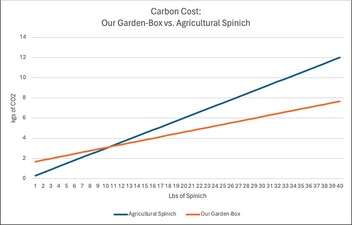
Figure 4: Graph comparing the carbon footprint of our design against the carbon footprint of
normal agriculture (Note: this is a rough draft of the graph, we plan on making a real graph)
Conclusions
In wrapping up our countertop-controlled environmental hydroponic system, we are excited about the potential positive impact on the carbon footprint within agriculture. The compact design allows for the cultivation of 4 to 8 plants, showcasing the efficiency of our prototype. Currently yielding substantial produce, specifically lettuce and spinach, our system demonstrates the viability of in-home hydroponics for fresh, sustainable harvests. Looking ahead we hope to integrate a humidity sensor, a TDS sensor, and a nutrient pump, which will fortify the precision and capabilities of our device. In the weeks to come, we plan to incorporate these additional components, expanding the system's functionality. We eagerly anticipate seeing comparable hydroponic systems becoming integral parts of households around the globe!
The content & opinions in this article are the author’s and do not necessarily represent the views of AgriTechTomorrow
Comments (0)
This post does not have any comments. Be the first to leave a comment below.
Featured Product
